
Fig. 2. Tuning the magnetic anisotropy of the free layer by voltage using two pairs of electrodes.
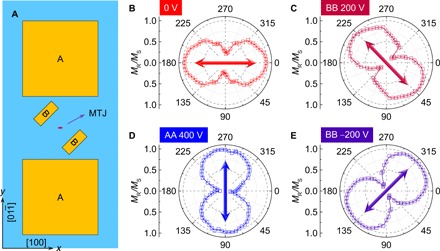
(A) Schematic top view of the sample structure with two pairs of AA and BB electrodes. An elliptical MTJ device of 18 × 6 μm2 was placed at the center of two electrode pairs. The major axis of the elliptical device was along the x axis. The pinning direction of the MTJ was along the [100] direction of the PMN-PT substrate (+x axis). The joint line of the AA electrodes was perpendicular to the pinning direction, while that of the BB electrodes deviated from the pinning direction by 45°. (B to E) Polar curves of the angular-dependent MR/MS of a CoFeB layer, when the applied voltages were 0 V (B), BB 200 V (C), AA 400 V (D), and BB −200 V (E). The [100] direction of the PMN-PT substrate was defined as 0°. The double-headed arrows indicate the direction of the magnetic easy axis.