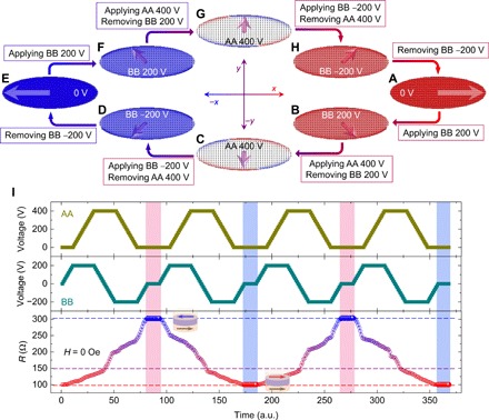
Fig. 3. Reversible and nonvolatile full control of MTJs by voltage-driven 180° magnetization switching.

(A to H) Simulated magnetization profiles of the free layer at various voltages applied to the AA and BB electrode pairs. A 180° magnetization switching was accomplished by implementing sequential voltages of 0 V (A) → BB 200 V (B) → AA 400 V (C) → BB −200 V (D) → 0 V (E) via successive unidirectional 45° rotations, and the M reverted back to the initial state after the same sequential voltages were implemented (E to H), suggesting reversibility and nonvolatility. The arrows schematically indicate the magnetization directions of the free layer. (I) Dependence of the resistance of an MTJ on voltage synergistically applied to the AA and BB electrode pairs at H = 0 Oe. The reversible resistance switching between high- and low-resistance states corresponds to the antiparallel and parallel magnetization configurations of the MTJ, as illustrated by the insets, which indicates the 180° magnetization switching of the free layer driven by voltage. The red, purple, and blue dashed lines denote the antiparallel, perpendicular, and parallel magnetization configurations of the MTJ, respectively. The stable resistance states with a giant modulation of approximately 200%, highlighted by the vertical pink and blue shaded lines, demonstrate that this 180° magnetization switching and full control of MTJs by voltage are reversible and nonvolatile.
