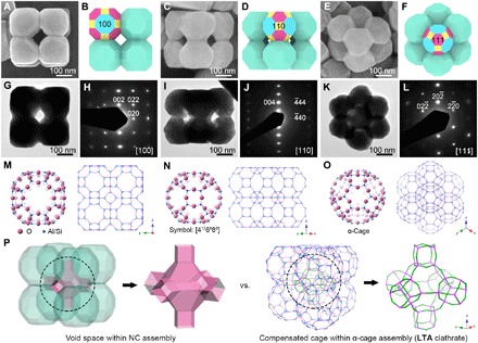
Fig. 1. Identification of Co-Fe PBA CC-1.

(A, C, and E) FESEM images, (B, D, and F) schematic models, (G, I, and K) TEM images, and (H, J, and L) SAED patterns of typical CC-1 particles from three directions of (A, B, G, and H) [100], (C, D, I, and J) [110], and (E, F, K, and L) [111]. Specific colors in the schematic models: blue, {100} facets; yellow, {110} facets; magenta, {111} facets. (M to O) Molecular frameworks of the LTA zeolite structure represented from different directions. The unit cell represented by the “ball & stick” model shows a supramolecular architecture of the α-cage. The “stick” models show a (2 × 2 × 2) supercell, displaying a typical LTA clathrate assembled from the α-cage building blocks. Na atoms and H2O molecules are omitted for clarity. (P) Comparison of the architecture between CC-1 and LTA clathrate.
