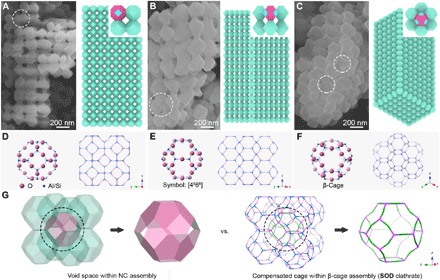
Fig. 2. Identification of Co-Fe PBA CC-2.

(A to C) FESEM images and corresponding schematic models of the typical CC-2 particles from different directions. Specific colors in the schematic models: blue, {100} facets; magenta, {111} facets. Some defects in the colloidal superlattices are located by white dotted circles in the FESEM images. (D to F) Molecular frameworks of the SOD zeolite structure represented from different directions. The unit cell represented by the “ball & stick” model shows a supramolecular architecture of the β-cage. The “stick” models show a (2 × 2 × 2) supercell, displaying a typical SOD clathrate assembled from the β-cage building blocks. Na atoms and H2O molecules are omitted for clarity. (G) Comparison of the architecture between CC-2 and SOD clathrate.
