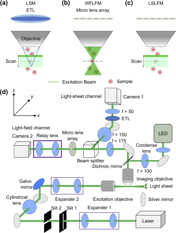
Fig. 1.
Conceptual schematics show that the LSLFM simplified the detection (vs. LSM) and limited the illumination to the region of interest for volumetric imaging (vs. WFLFM). (a) LSM used a scanning light-sheet excitation matched to an imaging plane modulated by an ETL. Dark green: excitation laser beam. Light green: Scanning volume of light-sheet. Dark blue and light blue lines represent the imaging paths focused at two positions controlled by the ETL that matched the excitation planes. (b) WFLFM used wide-field illumination and light-field imaging. (c) LSLFM used a scanning light-sheet for excitation and a micro-lens array for light-field imaging. (d) Schematic drawing shows the imaging setup.

