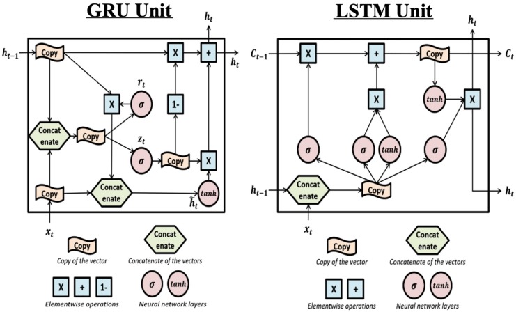
FIGURE 4.
The structure of Gated Recurrent Unit and Long Short-Term Memory units: Left: this is the structure of the Gated Recurrent Unit (GRU). The “update gate” zt is used to determine if the update will be applied to ht. rt is the “reset gate” and is used to determine if the previous hidden value (also the output value) ht–1 will be kept in the memory. The effects of the two gates are achieved by sigmoid activation functions which can be learned during training. Right: The structure of the Long Short-Term Memory (LSTM) unit. LSTM is complex and includes one more hidden value Ct and more gates compared to GRU. Each gate can be seen in the plot where the σ sign appears (i.e., sigmoid activation function). The first σ is the “forget gate” which controls whether previous hidden value, Ct–v will be used to calculate current output and kept in the memory. The second σ is the “input gate” which controls whether the new input will be used to calculate current output. The third σ is the “output gate” which filters the output, i.e., controls what part of the output values to send out as ht.

