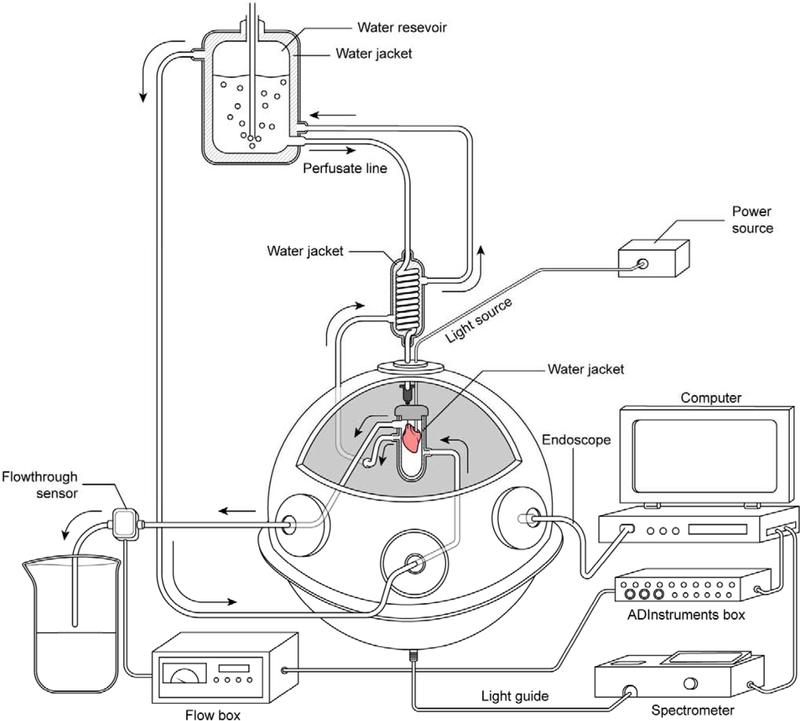
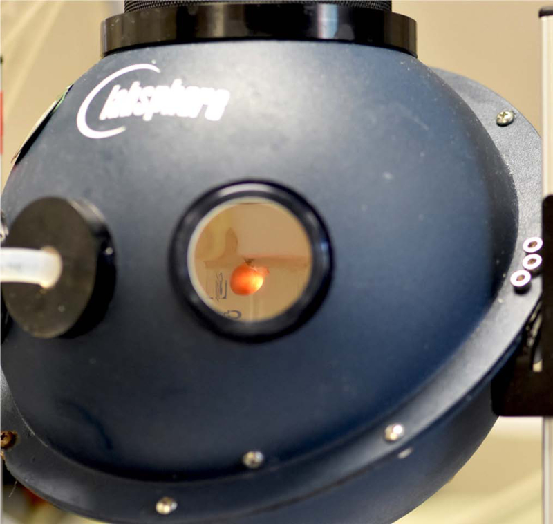
Figure 2:
Integrating sphere light collection system for perfused heart. A) Schematic representation of transmural spectroscopy in the integrating sphere. The side firing catheter is placed in the heart, which is bathed in a sealed water jacketed all glass chamber. The chamber is then placed in the center of an integrating sphere with the light detector on the bottom of the sphere. The bottom of the water jacketed glass chamber is made white to prevent light from striking the detector at the bottom of the sphere directly. The perfusion pressure is maintained at 70 mm Hg by regulated gas pressure over the water jacketed perfusate chamber. The light collected from the heart is directed to a rapid scanning spectrophotometer coupled to a data collecting computer. Coronary flow is monitored as the outflow from the glass chamber and recorded in a computer. An endoscope is inserted in one of the sampling ports of the sphere to permit online visual monitoring of the heart during an experimental procedure. Note the circulating thermoregulated water was maintained at 37 C ° with a temperature regulated circulating bath (not shown for simplicity). B) Image of perfused murine heart with ventricular cavity light source in center mounted position of integrating sphere. The light detector is at the bottom of the integrating sphere collecting all the light transmitted through the heart with little or no geometric selection preference. See Figure 2 for schematic. For the purposes of this picture one of the ports was removed to permit the photography, under normal conditions the sphere is closed to minimize non-reflective surfaces.


