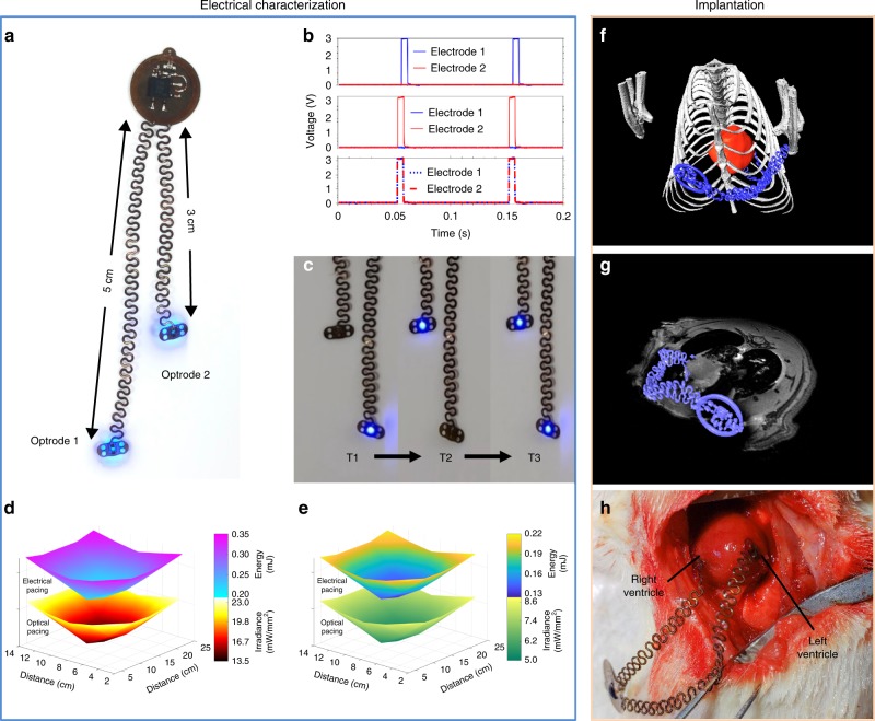
Fig. 3. Multisite pacing.
a Photographic image of a bilateral optogenetic stimulator. b Time-resolved voltage of pacing electrodes in a unilateral pacing mode for electrode 1 and 2, and in a bilateral pacing mode. c Independently addressable bilateral optogenetic stimulation at intervals T1, left optrode activation, T2 right optrode activation, and T3 simultaneous activation. d Spatially resolved energy and irradiance distribution of individual optrodes for independent bilateral electrical and optical pacing in a test cage at a height of 3 cm from the floor. e Spatially resolved energy and irradiance distribution for individual optrodes for combined bilateral electrical and optical pacing in a test cage at a height of 3 cm from the floor. f 3D rendering of an implanted device in a rat derived from combined MRI and CT images. g Combined 3D CT and 2D MRI slice of a bilateral pacemaker implanted in a rat, indicating epicardial positioning of optrodes. h In vivo surgical implantation of the device on a rat heart.

