
Figure 2.
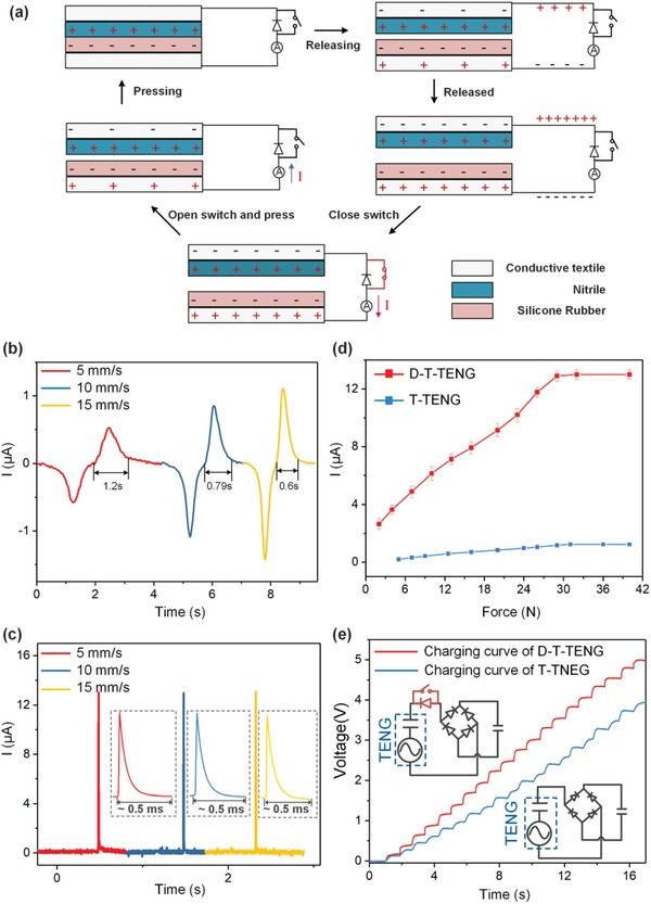
Basic characterization of the D‐T‐TENG. a) Working mechanism of the D‐T‐TENG. Current waveform of the b) T‐TENG and c) D‐T‐TENG under pressing/ releasing speed of 5, 10, and 15 mm s−1. d) Peak current of the D‐T‐TENG and T‐TENG as a function of applied forces at a constant pressing/releasing speed of 15 mm s−1. e) Charging curve of the D‐T‐TENG and T‐TENG on a 1 µF capacitor. The upper inset shows the circuit diagram of the D‐T‐TENG, and the bottom one is the circuit diagram for T‐TENG.