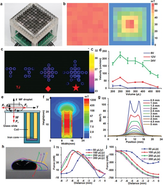
Figure 3.

Driving ADs through an electromagnetic platform. a) 10 × 10 arrays of electromagnets driven by a backplane formed by diodes and relays. b) Homogenous and inhomogeneous distribution for the electromagnetic field, defined by applied voltages to an individual electromagnet. c) Thermal images of different patterns generated due to repeated cycling of designated electromagnets. The cycling paths were predefined to form patterns, such as letters, diamonds, and stars. d) Velocities of varied volumes of droplets driven by the electromagnetic platform at different voltages. e) A diagram that shows the structures and components used for simulation. f) Distribution of magnetic field surrounding the electromagnet. g) Magnitude of B field of the electromagnet with varied distances. h) Outlines of shape changes of a droplet when the droplet moved from one electromagnet to the other. All outlines were superposed together to assist visualization and labeled with numbers to indicate the sequence in which the deformation happened. Simulated magnetic forces along i) vertical and j) horizontal directions applied on the moving droplet
