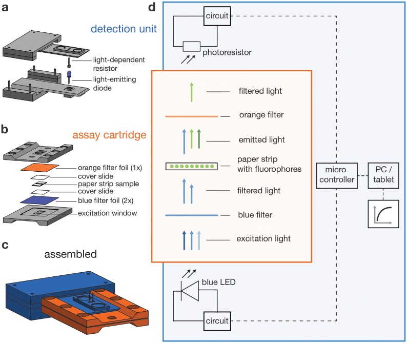
Fig 2. Detector operating principle.
(a) The detector body includes the electronics and two flexible levers that extend to the LED and LDR. (b) The assay cartridge is made from two identical sides, each covered with lighting filter foils between which the filter paper containing the sample is placed, protected by two cover slides. (c) Sketch of the assembled detector. (d) Schematic illustrating the light path and electronic modules of the detector.

