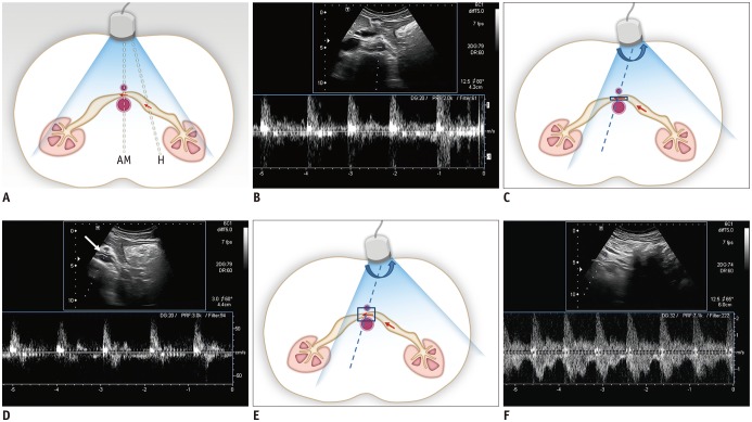
Fig. 5. Schematic drawing of Doppler US of LRV and spectral Doppler US images of LRV.
A. With usual position of US transducer in transverse plane, Doppler angle is optimal to obtain clear spectrum for hilar portion of LRV (H), while angle for AM portion of LRV is around 90°. Arrows indicate direction of blood flow and dotted lines indicate direction of ultrasound beam. B. Spectral Doppler US image of LRV obtained at AM portion shows noisy spectrum from aorta. Therefore, it is almost impossible to measure flow velocity in LRV. C. With slight shift of transducer to left and subtle counterclockwise rotation (curved arrow) until AM portion of LRV is located in left corner of US image, Doppler angle for AM portion of LRV can be adjusted. Arrows indicate direction of blood flow and dotted line indicates direction of ultrasound beam. D. Even with adjustment of Doppler angle, Doppler spectrum from LRV is still not clear, because LRV is not properly located due to small sample volume (arrow). E. In addition to adjustment of Doppler angle, increasing sample volume may help LRV be continuously included within sample volume between pulsating aorta and SMA. Arrows indicate direction of blood flow and dotted line indicates direction of ultrasound beam. F. Doppler spectrum from LRV now becomes optimal, with PV of approximately 150 cm/s.

