Figure 2.
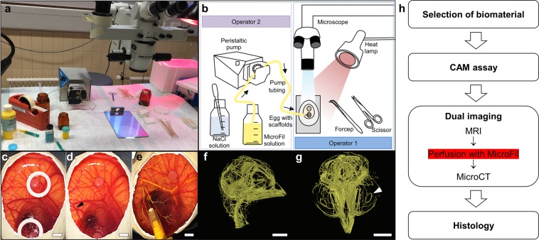
Setup for the pump-assisted CAM perfusion. (a) Photograph shows the setup of the workstation and equipment for the pump-assisted perfusion of the CAM with radiopaque MicroFil by two operators. (b) Detailed schematic drawing of the required equipment. Operator 2 operates the pump and sprinkles the CAM with NaCl solution to avoid dehydration during the perfusion process before Operator 1 places the needle of the MicroFil tube under microscopic view into a superficial blood vessel. (c) Scaffold (black dotted line) was incubated on the CAM for 7 days stabilized by a silicone ring. (d) The ring is removed for perfusion and a suitable vessel for the puncture site is selected (arrow). (e) The exchange of blood with the yellow MicroFil reagent indicates successful perfusion of the vessels. (f) MicroCT image of lateral view of the MicroFil-perfused chicken embryo head. (g) Coronal view of the MicroFil-perfused chicken embryo head. The white arrow indicates the major circulus arteriosus of the iris. We refer the reader to Supplementary Video S1. (h) Flowchart shows the whole process needed to evaluate a biomaterial for angiogenesis using the novel multimodal MRI and MicroCT imaging approach. The pump-assisted perfusion with MicroFil is performed after the MRI measurement. Scale bars = 500 μm.

