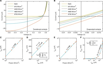
Fig. 3. Comparison of devices with transferred and directly evaporated top metal contacts.

(A and B) Power-dependent I-V characteristics of devices with transferred (A) and evaporated (B) Au top contacts taken under excitation with a 633-nm laser focused to a spot size of ~1 μm2. (C and E) Short-circuit current of devices with transferred (C) and evaporated (E) Au contacts. Symbols, measurements; line, power law fit. (D and F) Open-circuit voltage of devices with transferred (D) and evaporated (F) Au contacts. Symbols, measurements; line, fit. Insets show representative circuit diagrams. n is the ideality factor, and I0 is the dark saturation current extracted from the diode fit in (D). R is the resistance extracted from the linear fit in (F).
