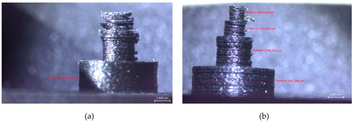
Figure 6.
A detailed view of the benchmark part showing the bosses positioned on top of each other with nominal dimensions of (from bottom to up) 5 mm, 2 mm, 1 mm and 0.5 mm (a) Left figure shows the resulting geometry when “expand thin features” is not turned on (b) Right figure shows the resulting geometry when “expand thin features” option is activated.

