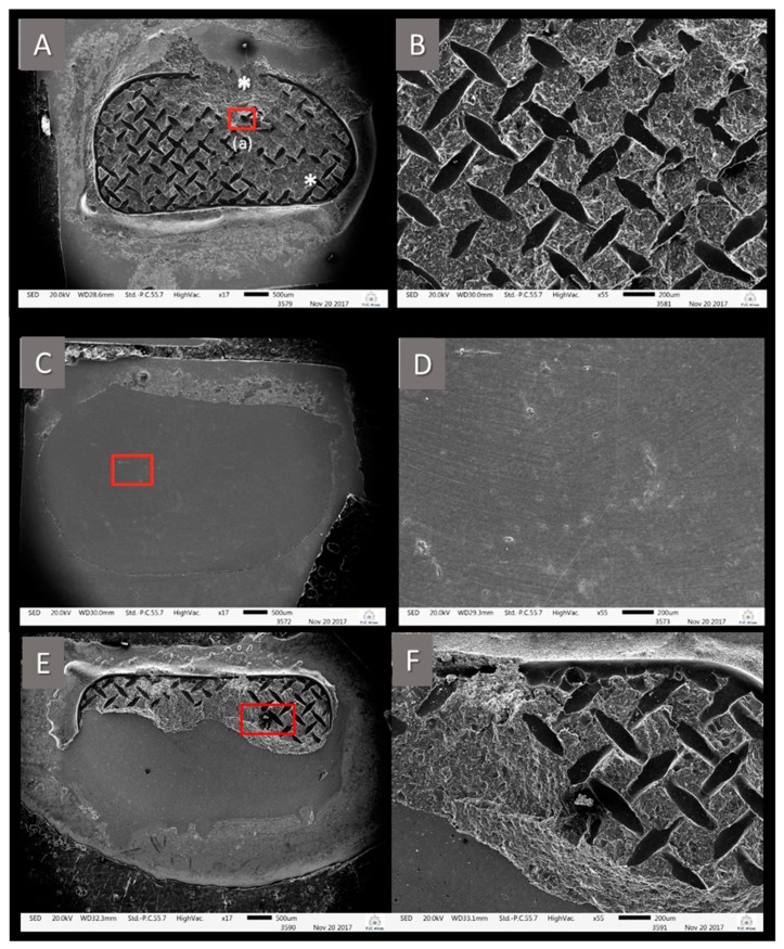
Figure 2.
SEM images showing different failure patterns. (A) (17× magnification) shows almost the entire interior design of the orthodontic tube used. The structure of the resinous material remained almost entirely on the ceramic, except for the region marked with *. (B) (55× of magnification) represents the region marked by the red square at (A). This fracture is classified as ARI 1, 100% of the resin attached to the zirconia. (C) (17× of magnification) is representative of the ARI 5 (no resin over the zirconia). In its high magnification (D) (55× of magnification) of the region marked with the red square, zirconia is free of resinous material. (E) (17× of magnification) represents the fracture pattern ARI 3, 10%–89% of the resin material attached to the ceramic. The image shows a mixed failure mode, as there was a displacement of the resinous material from the orthodontic tube, cohesive fracture of this same resinous material which is visualized in image (F), (55× magnification), and there is ceramic free of any resinous remnant.

