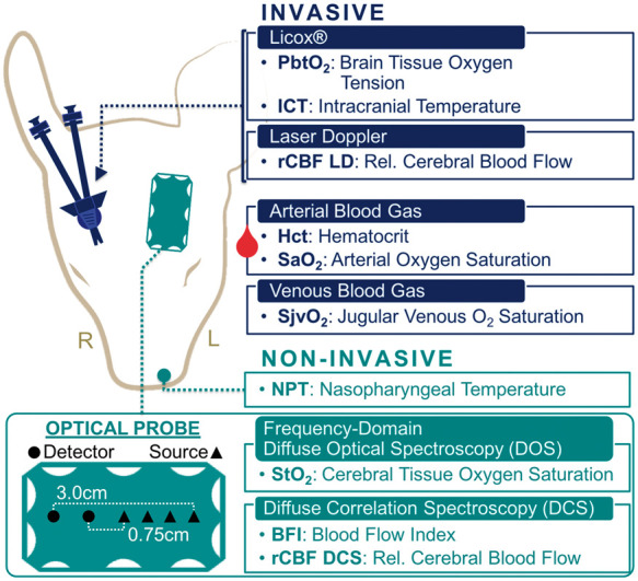
Figure 1.

Neuromonitoring – Head placement of non-invasive (green; left hemisphere) and invasive (blue; right hemisphere) neuromonitoring technologies. A diagram showing details about the FD-DOS/DCS optical probe is given on the lower left (source positions, triangles; detector positions, circles).
