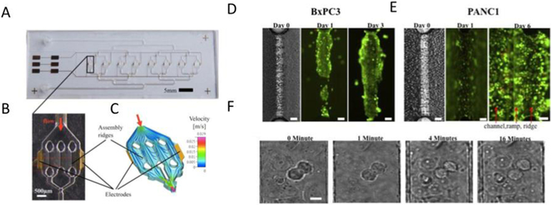
Figure 1:
Photographs and simulation of the HepaChip. (A) Image of the chip, with 8 culture chambers, fluid inlet and outlet and gold electrodes. (B) Enlarge view of single chamber, with 2 electrodes and 3 assembly ridges. (C) Simulation of the flow and cell trajectory inside of the culture chamber. (D) Live/dead staining of BxPC3, growing on the assembly ridge. (E) Live/dead staining of PANC1, spread on well channel walls and bottom. (F) Mitosis of MxPC3, observed after 16h culture. Reproduced under the terms of the Creative Commons License. [15] 2017 Nature.

