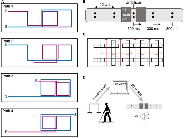
Figure 1.
Apparatus. (A) Four walking paths equated for difficulty (10 turns, ~127 ft in length; S = path start; F = path finish). Lines slightly offset and colored for clarity only. (B) Vibrotactile navigational belt schematic. Each dot represents a coin motor. Vibrotactile stimulation began below the umbilicus and moved towards the left or the right (a rightward movement is shown for illustration). (C) Room layout. Each square represents a 2 ft. × 2 ft. mat. Red lines show the participant localization laser transmitter-receiver grid. (D) Systems overview. Image of person walking with cane is modified from ID 45773820 © Anastasia Popova ∣ Dreamstime.com.

