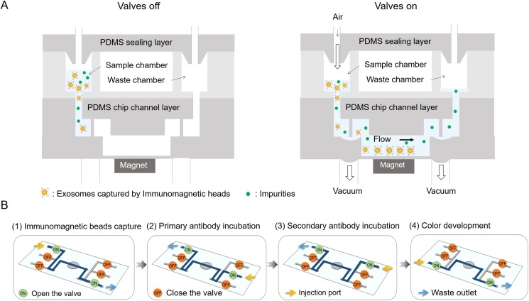
FIG. 2.
Illustration of the operation of the microfluidic device. (a) Schematic diagrams of the microfluidic device when valves were in and out. Magnetic beads with bound exosomes were then pumped into the reaction chamber and retained as a tight aggregate with the aid of magnetic force. Gas pressure was used to drive fluid, and vacuum was used to open the valves. (b) The switch state of valves during different processes.

