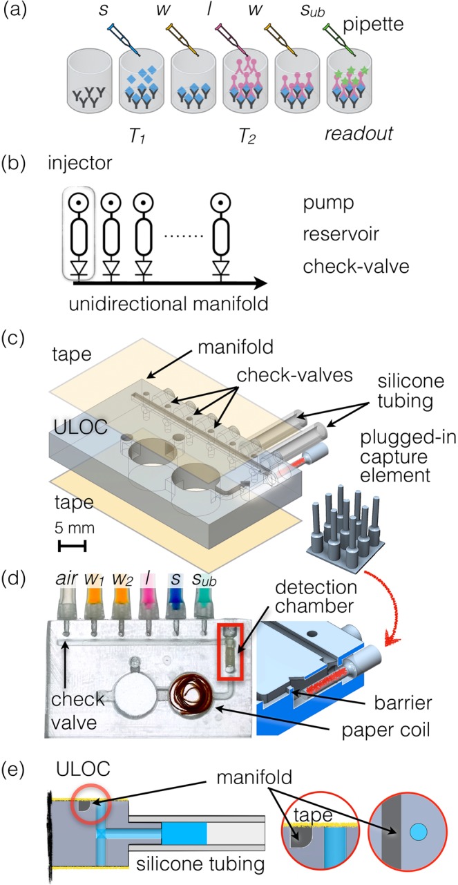
Figure 1.

(a) Scheme of ELISA assay performed on a microplate. The sample (s) is pipetted into the functionalized well and after incubation (T1), washing buffer (w) is applied. Subsequently label (l) is pipetted and incubated (T2), followed by another washing procedure and a final delivery of enzyme substrate (sub) for readout at a defined endpoint. (b) Scheme of the unidirectional manifold served by multiple injectors composed by a pumping element, a reservoir and a check-valve. (c) ULOC of 3D CAD highlighting the valve configuration and plugs to silicon tubing pumps, as well as the montage of the separately functionalized plugged-in capture element into the detection chamber, and the tape sealing. The inset show the separate 3D printout of the detection chamber elements. (d) Image of an assembled device ready for operation. The 3D model underscores the plug-in functional element and the geometric barrier assisting volume metering. (e) Detail of the injector with the check-valve body showing the 500 μm long barrier between the valve and the manifold, and the role of the sealing tape as elastic element to control unidirectional flow towards the manifold.
