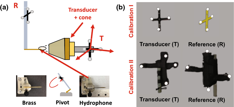
Figure 1 –
(a) Setup used for optically-tracked calibration. The brass tip offset from rigid-body tracker R is measured using a standard pivot test, then replaced with the real hydrophone. Beam mapping is performed with tracker T mounted to the transducer cone, and the hydrophone tip localized in the T coordinate frame. A skull piece appears in the image, but calibration beam maps were collected without the skull. (b) Calibration I used the top set of trackers, and Calibration II used the bottom set, which are larger and MR safe. During MR targeting, the R tracker is used as a global reference. The bottom set were wrapped in black tape to reduce optical reflections.

