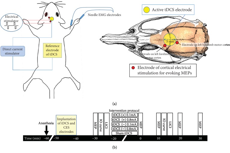
Figure 1.
Placement and assembly of tDCS and CES electrodes. (a) Schematic diagram of the experimental design for testing changes in motor plasticity after tDCS in anesthetized rats. The center of epicranial tDCS tube electrodes is positioned at 0 mm left and 2.5 mm posterior to the bregma. A cortical epicranial electrode is fixed with dental cement. An active electrode is fixed to the skull with dental cement, and a reference electrode is placed into the abdominal region. Wires in the socket are wrapped to screw electrodes for eliciting motor evoked potentials (MEPs). (b) Following implantation of tDCS and CES electrodes, measurements of the MEP amplitude were assessed at baseline before tDCS and at every 10 min for up to 30 min after the end of tDCS. One block of the baseline input-output (IO) curve and one block of baseline long-interval intracortical inhibition (LICI) were recorded. After tDCS intervention, one block of the IO curve and one block of LICI were measured at 12 min and 15 min, respectively, after the end of tDCS intervention.

