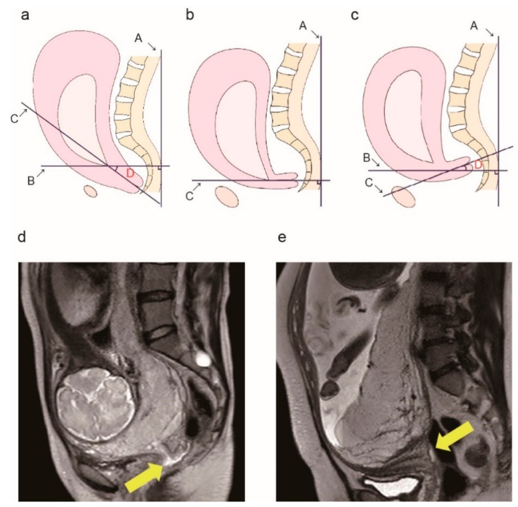
Figure 2.
Measurement of the cervical canal angle. (a) Diagram showing the method used to measure the cervical canal angle. Line A: A straight line through the broad of the back. Line B: A line perpendicular to line A. Line C: A line passing through the internal os to the external os (cervical canal line). D: The angle formed by lines B and C (defined as the cervical canal angle). (b) The cervical canal angle is 0° because lines A and C are perpendicular to each other. We defined this angle as the reference. (c) A sample image of a positive horizontal sign. Cervical canal is at a 10° angle counterclockwise along line B, thus the cervical canal angle is −10°. Typical magnetic resonance imaging (MRI) findings in a patient without posterior extrauterine wall adhesion (d) and a patient with posterior extrauterine wall adhesion (e). Yellow arrows indicate the cervical canal.

