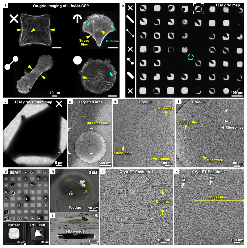
Figure 2. Cryo-EM grid micropatterning tailored for controlling cellular morphology and cytoskeletal architecture.
(a) On-grid (gold-mesh, SiO2 film R1/4) live-cell confocal microscopy of the actin organization in RPE1 LifeAct-GFP cells grown on complex micropatterns. Pattern designs are indicated at the top left of each of the light microscopy images. Positioning of actin stress fibers (yellow arrowheads) correlates with the distinct patterns. Blue arrowheads: actin bundles arranged into an arc or ring structure. (b-f) Cellular cryo-ET of RPE1 cells in peripheral thin regions (gold-mesh, SiO2 film R1/4). (b) Cryo TEM map of grid with 8 x 7 patterned grid squares. Patterns per row are indicated (left column). Cyan circle: grid center. (c) Cryo-TEM micrograph of a grid square of the framed cell in (b) grown on a cross-shaped pattern. (d) Magnified cryo-TEM micrograph of the framed area in (c), targeted for tomography. (e) Tomographic slice of the specified area in (d), 6.8 nm thickness, showing the organization of actin filaments into a stress fiber and an isotropic meshwork in the adjacent cellular protrusion. For full tomogram, see Supplementary Video 2. (f) Tomographic slice of the periphery of another cell grown on an oval-shape pattern depicting actin meshwork, bundles, and unidentified hexameric macromolecular complexes in the vicinity of the basal and apical cell membranes (inset: arrowheads). For full tomogram, see Supplementary Video 3. (g-k) Cellular thinning by cryo-FIB followed by cryo-ET. (g) SEM of RPE1 cells on a patterned titanium-mesh (SiO2 film R1.2/20) grid and overlaid with an image of the patterns. Bottom panels: gold-mesh, SiO2 film R1/4 grid. Left: 2 keV SEM image of a cross-shaped micropatterned grid square. Right: SEM of RPE1 cell spreading on a cross-shaped pattern. (h) SEM of a cell grown on a crossbow-shaped pattern (yellow) overlaid with the SEM micrograph of a wedge (top view) produced by cryo-FIB milling (titanium-mesh, SiO2 film R1.2/20). Squares indicate the positions of tomographic slices in (j) and (k). (i) Upper panel: FIB shallow angle view on cell in (h). Yellow rectangle indicates the pattern for milling. A thin wedge at the basal cell membrane is produced by ablating the top of the cell. Lower panel: cell after milling. (j, k) Tomographic slices of positions 1 and 2 indicated in (h). Actin bundles likely equivalent to actin transverse arcs (j) and internal stress fibers (k) are found in locations expected according to the actin map in a crossbow-shaped RPE1 cell (a).

