Figure 3.
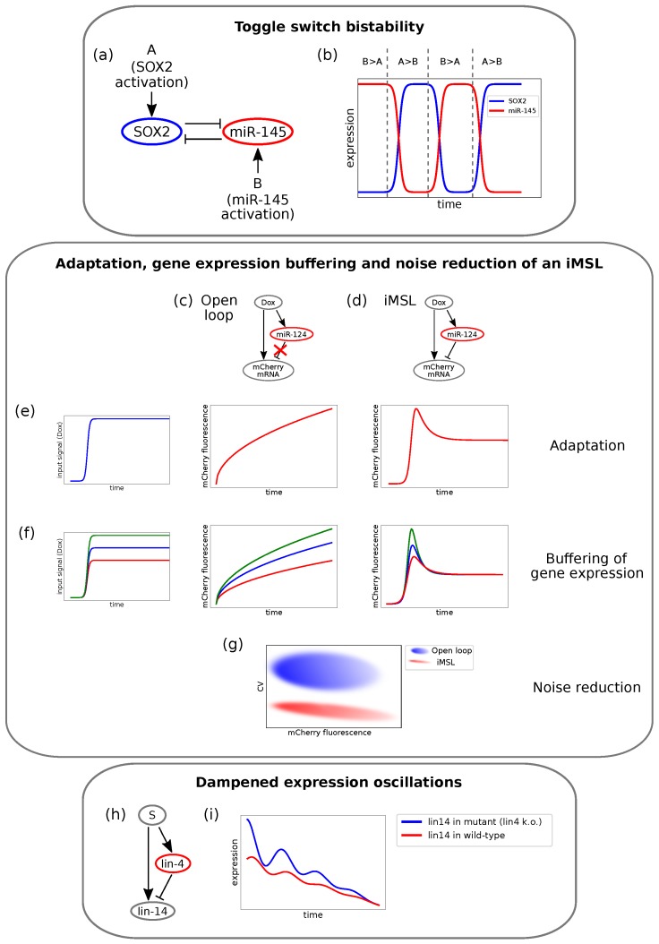
Examples of different experimental circuits showing properties theoretically predicted. (a) Example of the double negative feedback loop (DNFL) that displays bistability described in Fang et al. [100]. The circuit involves SOX2 and miR-145. (b) Bistable output of the DNFL. SOX2 temporal expression is depicted in blue and miR-145 temporal expression in red. The relative activation strengths determine whether the system settles in the high-miR-145 state or in the high-SOX2 state. Panels (c–g) report a schema of the results obtained by Strovas and colleagues [147] for an intronic miRNA mediated self-loop (iMSL). (c) The engineered open-loop. (d) The engineered iMSL. (e) Unlike the open-loop, the iMSL displays output adaptation. When a sudden input (left panel) is given to the system, the output fluorescence of the open-loop responds with an increasing trend (central panel), while the iMSL produces a pulse before reaching a lower steady-state level (right panel). (f) In the open-loop case (central panel), output levels depend on input signal intensities (left panel). On the contrary, the adaptive output level of the iMSL does not depend on the input size, and the iMSL buffers gene expression (right panel). (g) The iMSL displays noise reduction: for a given mean fluorescence value, the coefficient of variation (CV) is significantly lower in the iMSL case (in red) than in the open-loop (in blue). (h) The iFFL addressed by Kim and co-workers [120]. Lin-4 and lin-14 miRNAs are both transcribed by an upstream TF and lin-4 post-transcriptionally targets lin-14. (i) Lin-14 temporal expression in wild-type C. elegans (blue) and in mutant with lin-4 transcription knock-out (red). Lin-14 oscillation are dampened by lin-4 pulsatile expression (adapted from [120]).

