
Fig. 5.
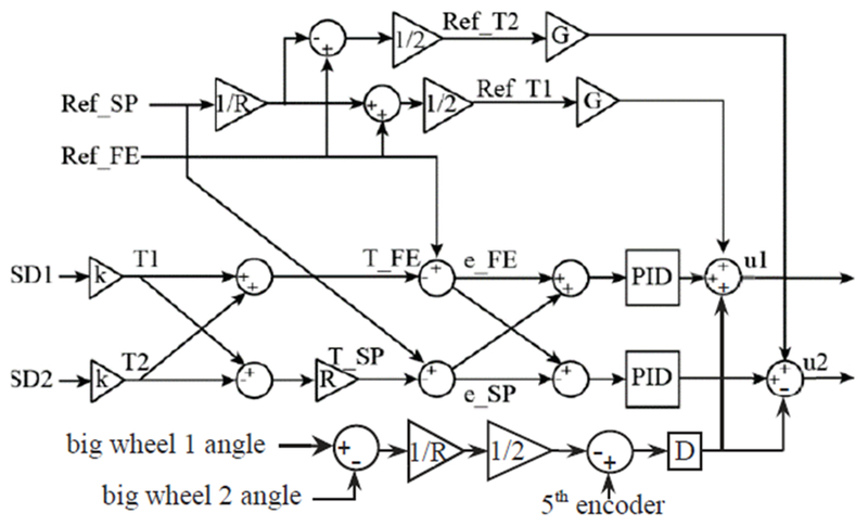
Control diagram illustrating torque control approach. Current spring deflections (SD1 and SD2) are the difference between encoders on each SEA. They are converted to current torque T1 and T2 through the SEE stiffness k, which varies nonlinearly with spring deflection. Flexion-extension torque and supination-pronation torque T_FE and T_SP are calculated according to (1) and (2). Ref_FE and Ref_SP represents reference torque in flexion-extension and supination-pronation. The flexion-extension torque error, e_FE, is feed into both controllers with the same sign so that both SEA can work together to decrease e_FE. The supination-pronation error, e_SP, is fed in to the controllers with opposite sign. At the output stage, control voltages voltage, u1 and u2, are sent to the motor amplifiers.