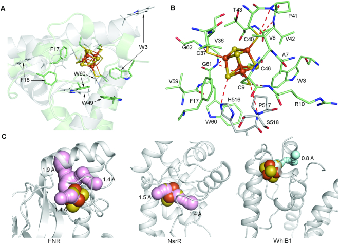
Figure 3.
Structural basis for the stability of the [4Fe–4S] cluster in the WhiB1:σACTD complex. (A) Comparison of the crystal structure of the σACTD–bound WhiB1 with the NMR structure of free WhiB1 (PDB ID: 5OAY) aligned at the Fe-S cluster binding site. Only the first model of the NMR structure is shown for clarity. The [4Fe–4S] cluster and the aromatic residues near the cluster for the σACTD–bound WhiB1 are shown in the ball-and-stick and stick representation, respectively; while their corresponding residues in free WhiB1 are shown in thin lines. The carbon atoms are colored pale green for the σACTD–bound WhiB1 and grey for free WhiB1. Other non-carbon atoms in this figure are colored by the element type: blue for N, red for O, orange for Fe and orange and yellow for S. (B) Stick representation of the local environment of the [4Fe–4S] cluster binding pocket. The [4Fe–4S] cluster is shown in ball-and-stick representation. The carbon atoms are colored pale green for WhiB1 and grey for σACTD. (C) Solvent-accessible paths from the surface towards the [4Fe–4S] cluster in FNR (PDB ID: 5E44) and NsrR (PDB ID:5N07) were calculated by CAVER with a shell radius of 1.4 Å, which is the assumed radius cutoff for solvent molecules. The paths are highlighted in pink and the minimum bottleneck of each path is indicated. No solvent-accessible path is found in the WhiB1:σACTD complex with a shell radius of 1.4 Å. Instead the largest tunnel found in the WhiB1:σACTD complex with the minimum bottleneck of 0.8 Å is shown for demonstration and is highlighted in cyan.

