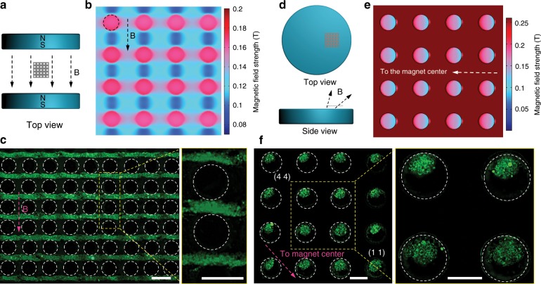
Fig. 2. Assembly of GUVs on the SS mesh under horizontal and inclined magnetic field.
a The schematic of the device for horizontal magnetic field. b Simulated magnetic field distribution on the top surface of the SS mesh under horizontal magnetic field. c Fluorescence images of the GUVs colonies formed under horizontal magnetic field. The right image is the enlarged image in the yellow dash box of the left image. d The schematic of the device for inclined magnetic field (with directions between the vertical and horizontal magnetic fields) by putting the SS mesh on one side of the top of the magnet. e Simulated magnetic field distribution at the bottom surface of the SS mesh under inclined magnetic field. f Fluorescence images of the GUVs colonies under inclined magnetic field. The right image is the enlarged image in the yellow dash box of the left image. The dash circles in b, c, e, and f indicate the microwells. The scale bars in c and f are 200 μm.

