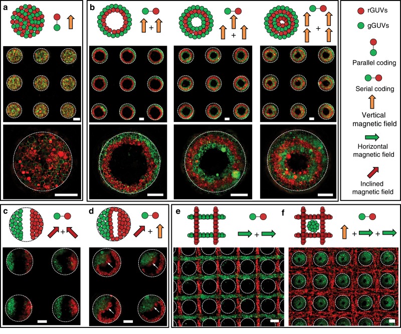
Fig. 3. Coding of spatially controlled GUVs colonies.
a Schematic and fluorescence images of GUVs colonies formed via the parallel coding of giant unilamellar vesicles with green fluorescence (gGUVs) and giant unilamellar vesicles with red fluorescence (rGUVs). Schematic and fluorescence images of the serially coded GUVs colonies via application of vertical magnetic field for the alternative assembly of gGUVs and rGUVs (b), successive application of two inclined magnetic fields with different directions respectively for gGUVs assembly (putting the SS mesh on one side of the magnet) and rGUVs (putting the SS mesh on the other side of the magnet) (c), successive application of inclined magnetic field for gGUVs assembly and vertical magnetic field for rGUVs assembly (d), successive application of two perpendicular horizontal magnetic fields for the chronological assembly of gGUVs and rGUVs (e), and successive application of vertical magnetic field for gGUVs assembly and two perpendicular horizontal magnetic fields for rGUVs assembly (f). The dash circles indicated the microwell wall. The scale bars are 100 μm.

