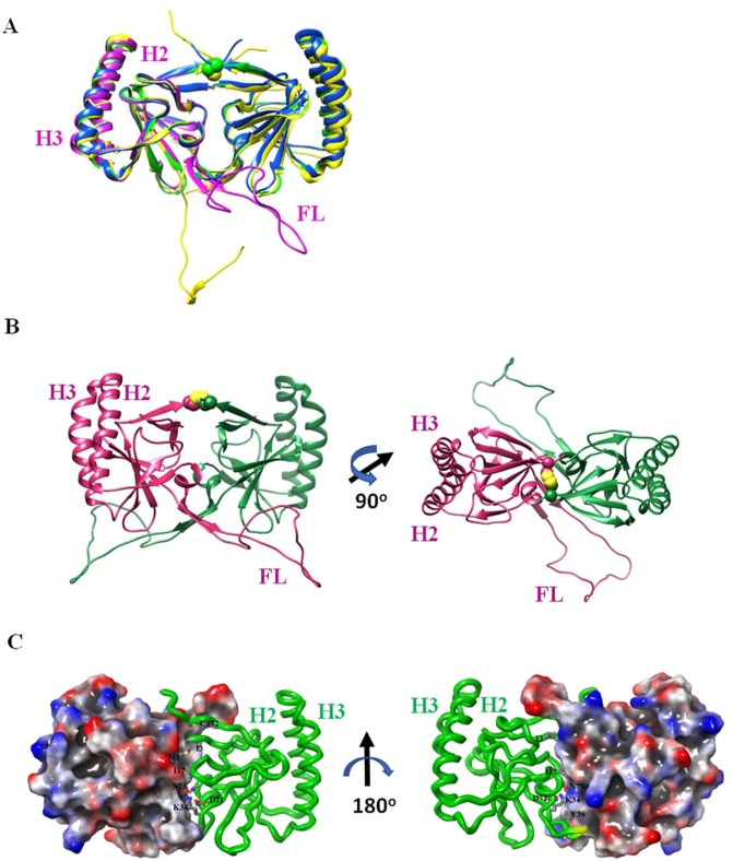
Figure 6.
Crystal structures of f-dTCTP and ∆-dTCTP. (A) The comparison of 3D-structures of f-dTCTP (green) and Δ-dTCTP (blue) indicates that their overall architecture is conserved. They form a dimer mediated by Cys172 (yellow) which is depicted with a sphere model based on the crystal structure of f-dTCTP. The previously reported dimeric X-ray structure (5O9M, yellow) and a monomeric NMR structure (2HR9, pink) are also superimposed. (B) The modeled crystal structure of dimeric TCTP. Two subunits are colored in green and deep pink. The FL of TCTP determined by NMR is fused to the crystal structure of f-dTCTP where its FL is not determined. Among the NMR structures, a model avoiding collision when a dimeric form was constructed was selected. The modeled f-dTCTP is built by inserting the chosen FL between Ser37 and Ile67 of f-dTCTP. The right figure was drawn by rotating 90 degree of the left model. (C) The crystal structure of Δ-dTCTP. The crystal structure of Δ-dTCTP is drawn with an electrostatic potential surface (gradient from blue (positive) to red (negative)) of one subunit and a ribbon model (green) for the other. The residues on the dimeric interface are labeled and drawn with a ball-and-stick model. The secondary structure elements were also labeled with β for β-strands and H for α-helices. In the right figure, the yellow region of the ribbon model represents two glycine residues located on the loop between β5 and β6 (almost hidden in this view) genetically engineered to connect Ser37 and Ile67.

