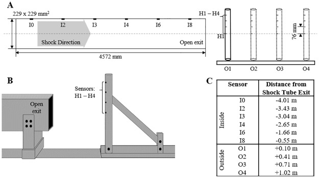
Fig 2. Schematic of the experimental setup used to create the validation dataset.
(A) A shock tube with a square cross section was used in the development of the experimental dataset. Incident pressures were measured at six locations within the shock tube (I0, I2-I4, I6, and I8). Total and incident pressures were measured at four longitudinal locations outside of the shock tube (O1-O4) at four vertical heights (H1-H4). (B) A schematic representation of the experimental setup for the O1-O4 tests, with the sensing apparatus in the total pressure orientation. (C) The locations of all sensors with respect to the shock tube exit. Negative values denote upstream distances, into the shock tube, and positive values indicate downstream distances.

