Fig. 2.
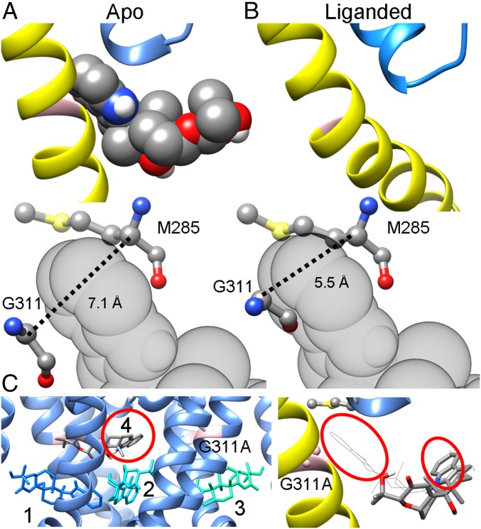
Differences in the dimensions of the crevice between the PH and S6 account for the state dependence of PAX inhibition. (A, Top) The most favored binding pose of PAX in the metal-free BK pore, with S6 and the selectivity filter shown in yellow and blue, respectively. (A, Bottom) The relative position of PAX to G311 in S6 and M285 in the PH, 2 residues lining opposite faces of the binding crevice. The dotted line marks the distance between the α-carbons of G311 and M285. (B, Top) The open mSlo1 pore viewed from the same perspective as in A. (B, Bottom) The distance between the α-carbons of G311 and M285 decreases from 7.1 Å in the closed structure to 5.5 Å in the open structure. As a result, PAX cannot fit into the S6-PH crevice. (C, Left) The top 4 binding poses of PAX in the closed mSlo1G311A structure. G311A is shown in pink to indicate the location of the PAX-binding crevice. The numbers represent the rank order of binding poses, with 1 being the best binding pose. The relative energies of binding poses 1 to 4 calculated by AutoDock Vina are (in kcal/mol) −9.1, −9.1, −9.0, and −9.0, respectively. It should be noted that even though binding pose 4 is close to the binding crevice, the orientation of PAX is opposite to that observed in the WT structure, with the indole ring (red circle) pointing into the central cavity but not into the binding crevice as in the WT structure. (C, Right) Close-up view of the PAX binding pose 4 (rendered as sticks) in a closed mSlo1G311A pore, with the same perspective and coloring scheme as in A and B. The most favored binding pose of PAX in the WT BK pore (rendered as wires) is included for comparison. The indole rings of both binding poses are denoted by red circles.

