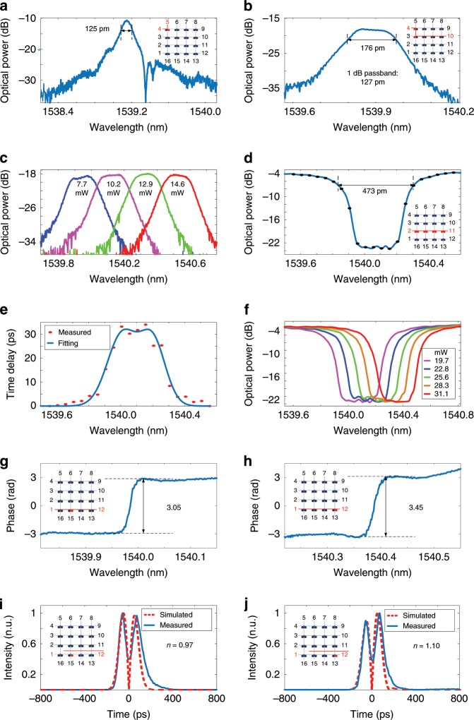
Fig. 3. Experimental results with FPDA reconfigured to perform multiple functions.
a Measured transmission spectrum at port 5 when an optical signal is applied to the chip via port 4. b Measured transmission spectrum at port 10 when the FPDA operates as a flat-top optical filter. c Center-frequency tuning of the flat-top optical filter. d Measured transmission spectrum at port 11 when an optical signal is applied to the chip via port 2. e Measured group delay. f Center-frequency tuning of the delay line. g Measured phase response of the 3rd MDR from the left in the channel from port 1 to port 12. h Measured phase response of the 8th MDR. i Measured differentiated Gaussian pulse when the 3rd MDR works as a temporal differentiator. j Measured differentiated Gaussian pulse when the 8th MDR works as a temporal differentiator.

