Figure 2.

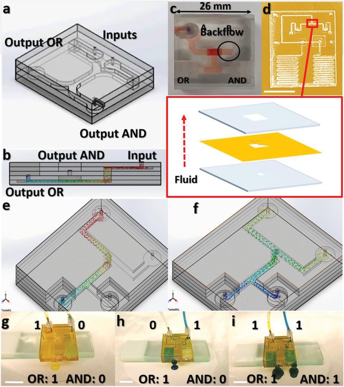
Microfluidic chip fabrication and design optimization. a) 3D microfluidic chip with multilevels of PMMA sheets. Microchannels are fabricated using CO2 laser followed by thermocompression of the different layers. b) Cross‐sectional illustration showing the fluid flow in the microchannels. c) Fabricated microfluidic chip showing a challenge of fluid backflow into the inputs. d) Optimized microfluidic chip design with scaled down microchannels and a flexible polyimide sheet embedded between the PMMA sheets to enable one‐directional flow of fluid. Inset shows the stack of the rigid PMMA and flexible polyimide sheets for fluid backflow blockade. Scale bar: 1 cm. Simulated 3D microfluidic chip showing the AND/OR outputs for e) A = 1 and B = 0, and f) A = 1 and B = 1. g) Optical image of the operation of the microfluidic chip with inputs A = 1 and B = 0. Scale bar: 1 cm. h) Optical image of the operation of the microfluidic chip with inputs A = 0 and B = 1. Scale bar: 1 cm. i) Optical image of the operation of the microfluidic chip with inputs A = 1 and B = 1. Scale bar: 1 cm.
