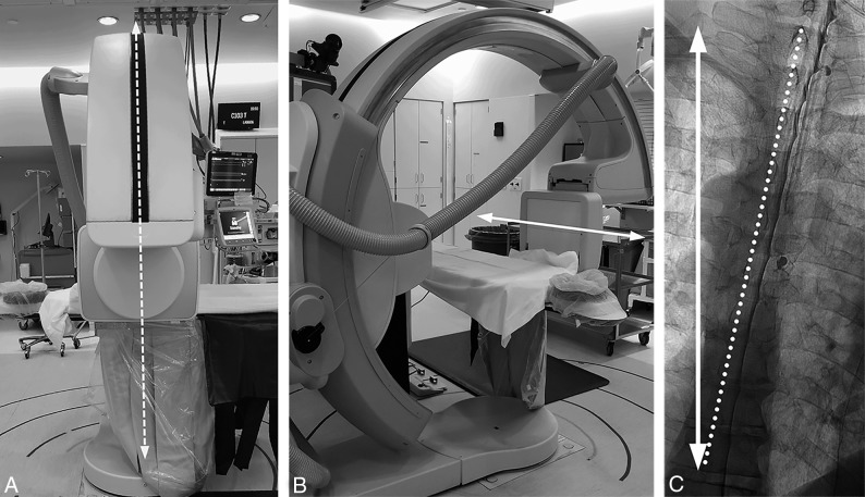
Fig 4.
Defining the true horizontal axis and spine tilt on DSM. By placing the C-arm in a vertical position with respect to the floor (A, dotted arrows) while maintaining the long axis of the image intensifier orthogonal to the C-arm (B, solid arrow), the long axis of the image intensifier and the long axis of the image are aligned horizontally, parallel to the floor (B and C, solid arrow). The angle between this line and the line connecting the spinous processes (C, dotted line) defines the spine tilt with respect to the floor.

