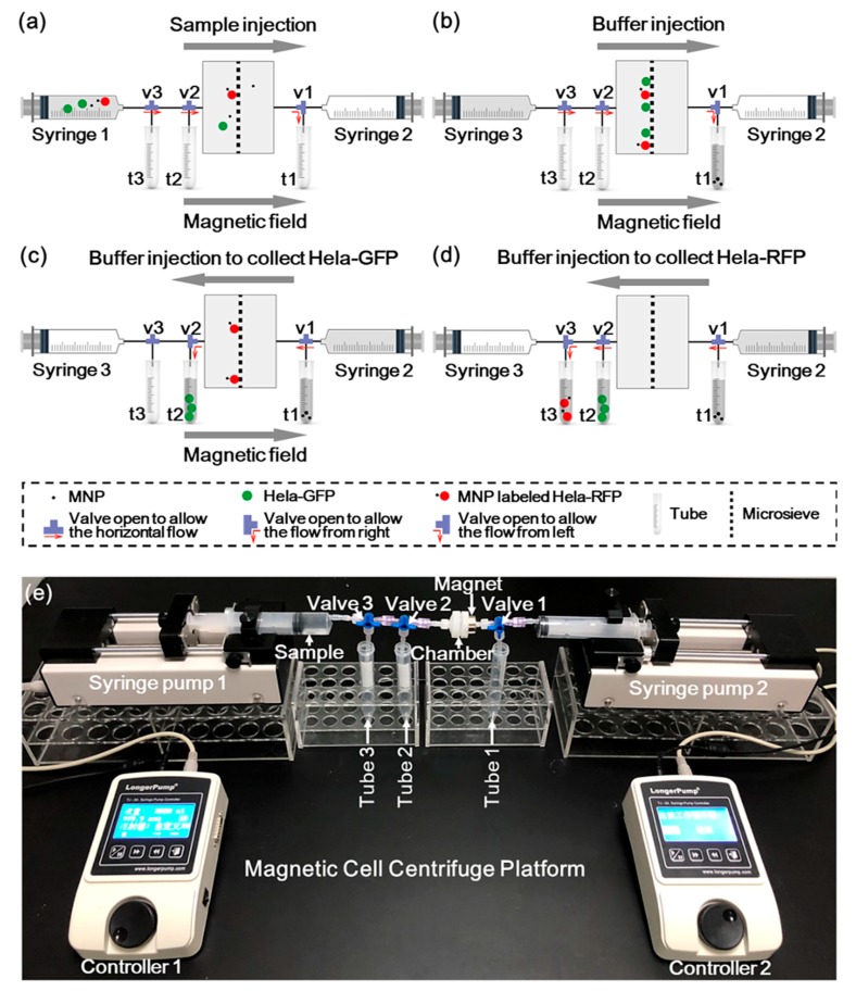
Figure 3.
Illustration of the MCCP operation process: (a) The sample was injected into the chamber under a constant flow rate of 2 μL/s by syringe 1. (b) The buffer was injected by syringe 3 to flush the cells with that in the piping system all into the microsieve chamber. (c) The buffer was injected by syringe 2 to collect the unlabeled Hela-GFP with the presence of a magnet. (d) The buffer was injected by syringe 2 to collect the MNPs-labeled Hela-RFP. (e) A picture of the experimental setup with constant flow rate condition of the MCCP.

