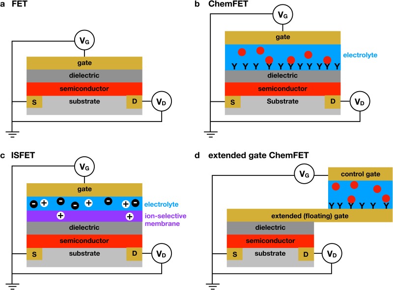
FIG. 1.
Different methods of FET-based detection. (a) Illustration of a standard field effect transistor (FET). The application of a gate voltage, , in excess of the threshold voltage, , causes the transistor to turn ON, leading to a measurable drain current, , between the source and drain electrodes under the application of the drain voltage, . (b) Illustration of a chemical field effect transistor (ChemFET).50 The aqueous electrolyte is contained between the dielectric and the gate electrode. Adsorption of a material to the dielectric surface, illustrated here as antibody/antigen binding, changes the properties of the dielectric, which then changes the threshold voltage required to turn the transistor ON. (c) Illustration of an ion-selective field effect transistor (ISFET).52 The ion selectivity can be provided by a selective membrane or an ion-selective oxide. Ions that penetrate the membrane polarize the dielectric. (d) Illustration of the extended-gate (or floating-gate) architecture.53 This approach decouples the transistor from the sensing medium, thereby greatly increasing the flexibility of the platform. The order of the layers for this extended gate example is chosen to provide easy comparison with the previous examples, not to reflect the actual fabrication of an extended gate device.

