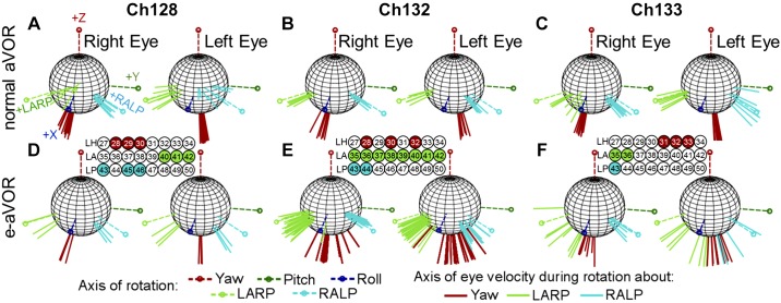
Fig. 6.
Electrically evoked angular vestibulo-ocular reflex (aVOR) from 3 chinchillas. A–F: to test whether the new electrode array and circuitry could replicate previous results to restore the angular VOR (Dai et al. 2011a; Della Santina et al. 2007), we compared normal eye movements collected before electrode implant (A–C) to electrically evoked eye movements (D–F) using electrode arrays targeting semicircular canals. Each spherical plot shows the normalized axes of rotation, Yaw, left-anterior/right-posterior (LARP), right-anterior/left-posterior (RALP), Pitch, and Roll. The axes represent the axis of eye velocity during a left-ward head movement for the normal data. In general, the axis of eye rotation is aligned with the axis of rotation (the canal axis). However, for Ch128 and Ch133, the right eye LARP response shows misalignment, which is possibly due to slight tethering from the scleral coil. For the electrically evoked aVOR (e-aVOR; D–F), each axis represents the normalized axis of eye velocity during peak positive stimulation. The rows of electrodes represent the 8 electrode contacts for the left horizontal (LH), left anterior (LA), and left posterior (LP) canals. Highlighted electrodes represent the contacts that elicited the best results within that canal.

