

Abstract
Aiming at solving the problem of high energy consumption in the rated belt speed operation of a belt conveyor system when the material flow rate is reduced, the power consumption of the frequency converter, motor, and belt conveyor is analyzed, a power consumption model of the belt conveyor system is established, the relationship between the power consumption of the belt conveyor system and belt speed is obtained, and a energy-saving control strategy of the belt conveyor with variable belt speed based on the material flow rate is put forward. The energy consumption of the belt conveyor is analyzed for a practical case. Results show that the power consumption model is accurate and the control strategy effectively reduces energy consumption. The model has high application value in coal, ports, power, mine, metallurgy, chemical, and other industries.
1. Introduction
The belt conveyor is used for continuous transportation in modern production. It has the advantages of large capacity, long distance, low energy consumption, low freight, high efficiency, smooth operation, and convenient loading and unloading, and is suited to bulk-material transportation. It has become one of the three main industrial transportation modes along with automobiles and trains and has been widely used in coal, ports, electricity, power, mining, metallurgy, chemical, and other industries. The operation of the belt conveyor consumes much electricity. It has been reported [1] that 41% of global electricity is provided by coal-fired power plants, and coal is one of the main sources of carbon dioxide emissions worldwide. It is therefore imperative to reduce the energy consumption of the belt conveyor system.
There are two ways to reduce the energy use of the belt conveyor: one being to improve the performance of the equipment and the other being to optimize operation parameters (e.g., the belt speed). Daijie He et al. [2] studied the transient operation dynamics of a conveyor belt while adjusting the speed of the belt conveyor and solved the time optimization problem of the speed adjustment. Other studies [3–5] focused on the belt conveyor and proposed a power-saving model for control of the speed of the belt conveyor. Through analysis of the energy model of the belt conveyor and ring hammer crusher, Shirong Zhang et al. [6] proposed a power-saving model. The problem with the above models is that they do not take the belt conveyor system as the research object but only consider the energy consumption of the belt conveyor itself.
Aiming to solve the problem of high energy consumption in the rated belt speed operation of the belt conveyor when the material flow rate is reduced, the present paper analyzes the power consumption of the frequency converter, motor, and belt conveyor, establishes a power consumption model of the belt conveyor system, and proposes a energy-saving control strategy for the belt conveyor with a variable belt speed based on the material flow rate. The energy consumption of the belt conveyor system is analyzed for a practical case. Results show that the power consumption model of the system is accurate and the energy-saving control strategy achieves the expected energy savings.
2. Power consumption model of the belt conveyor system
The belt conveyor system studied in this paper comprises a frequency converter, motor, and belt conveyor (Fig 1).
Fig 1. The system block diagram of the belt conveyor.

2.1 Power consumption of the belt conveyor
According to ISO 5048, when the length of the belt conveyor exceeds 80 meters or when a single conveyor has only one loading point, the resistance FU of the belt conveyor is
| (1) |
where C is the additional-resistance coefficient, FH is the main resistance, FS1 is the main special resistance, FS2 is the additional special resistance, and FSt is the lifting resistance.
If the belt speed of the belt conveyor is denoted v (unit: m/s) and the material flow rate is denoted M (unit: t/h), then
| (2) |
where qG is the linear density of the material (kg/m).
Considering Eq (2), the power consumption of the belt conveyor during stable operation is
| (3) |
This equation can be decomposed to
| (4) |
| (5) |
Obviously, pBC (v) only relates to the belt speed while pBC (M) only relates to the material flow rate.
2.2 Power consumption of the motor
The temperature change of the motor has little effect on the resistance and inductance parameters of the stator and rotor, and the effect of the temperature change of the motor is thus not considered in the analysis of the motor loss.
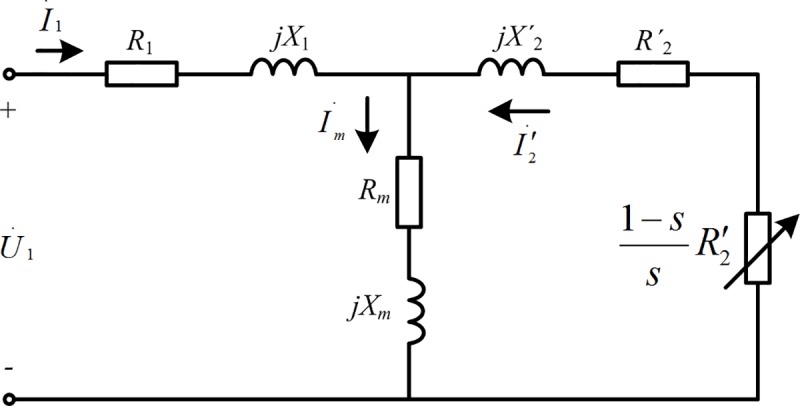
Fig 2 is the equivalent circuit diagram of a three-phase asynchronous motor running stably at speed n [7]. In Fig 2, is the phase voltage of the power supply, is the input current of the stator, is the excitation current, is the converted rotor circuit current, R1 is the stator winding resistance, X1 is the stator leakage reactance, Rm is the excitation resistance, Xm is the excitation reactance, R'2 is the converted rotor winding resistance, X'2 is the converted rotor leakage reactance, and is the equivalent load resistance after conversion.
Fig 2. The equivalent circuit diagram of three phase asynchronous motor in stable operation.
The current of the equivalent circuit is calculated as
| (6) |
| (7) |
| (8) |
where z1=R1+jX1, zm = Rm+jXm, and .
The stator copper loss, iron loss, and rotor copper loss of the motor are respectively
| (9) |
| (10) |
| (11) |
According to [8], the stray loss and mechanical loss account for about 20% of the total loss. The total loss of the three-phase asynchronous motor is therefore
| (12) |
The motor is regulated by frequency conversion through the frequency converter, and the reactance in the equivalent circuit thus changes with the frequency of the input power supply. Hence,
| (13) |
where f1 is the input frequency of the motor and Lx is the inductance.
As a coefficient related to the motor flux, α is defined as
| (14) |
Where N1 is the number of stator turns, kN1 is the winding factor and Φ is the main flux.
Under the condition of constant torque load, N1, kN1 and Φ are constants, so α is a constant. Therefore, for the same belt conveyor with constant torque load, α is a constant.
The stable operation of the belt conveyor relates to a constant torque load; i.e., α is a fixed value. The input voltage of the motor is therefore proportional to the frequency of the power supply:
| (15) |
The relationship between the stator speed and power frequency is
| (16) |
where p is the number of pole pairs of the motor.
The slip ratio is calculated as
| (17) |
where n1 is the synchronous speed (unit: r/min) and n is the rotor speed (unit: r/min).
Owing to the small change in the slip ratio, to simplify the calculation, it is assumed that the slip ratio is fixed and
| (18) |
It follows from the relationship between the linear speed and rotational speed that
| (19) |
where v is the running speed of the belt conveyor and R is the radius of the driving drum of the belt conveyor.
The relationship between the belt speed and the frequency of the output power supply of the frequency converter is therefore
| (20) |
The relationship between the supply phase voltage and belt speed is
| (21) |
The relationship between the impedance and belt speed is
| (22) |
On the basis of Eqs (6)–(11) and Eq (21), the stator copper loss, iron loss, and rotor copper loss are respectively
| (23) |
| (24) |
| (25) |
The power consumption of the motor is
| (26) |
Therefore, the power consumption of the motor is a function of the belt speed of the belt conveyor.
2.3 Power consumption of the frequency converter
The power loss of the frequency converter mainly comprises losses of the insulated-gate bipolar transistor (IGBT) and fast-recovery diode [9]. The fast-recovery diode has power loss at the moments of switching on and off but its leakage current is low when it is off, and the turn-on loss is thus negligible compared with the turn-off loss [10].
Fig 3 shows the main circuit of the frequency converter, including the rectifier, inverter, and intermediate circuit. The turn-on and turn-off of the inverter are controlled by the SVPWM pulse.
Fig 3. The main circuit of the frequency converter.

The on-state loss of the IGBT is [11, 12]
| (27) |
where m is the modulation ratio, cosφ is the power factor, rCE is the on-state resistance of the IGBT, VCEO is the actual on-state voltage drop of the IGBT, and ICM is the peak of effective current.
The on-state loss of the fast recovery diode is
| (28) |
where rF is the on-state resistance of the fast-recovery diode while VFO is the actual on-state voltage drop of the diode.
The switching loss of the IGBT is
| (29) |
where fSW is the switching frequency, Vdc is the DC bus voltage, VCEN is the rated voltage, ICN is the rated current, Esw(on) is the instantaneous energy loss of the IGBT each time that it shifts from the turned-off state to the turned-on state under the rated current ICN and rated voltage VCEN, and Esw(off) is the instantaneous energy loss of the IGBT each time that it shifts from the turned-on state to the turned-off state under the rated current ICN and rated voltage VCEN.
The power consumption of the frequency converter is obtained from Eqs (27)–(29) as
| (30) |
where and
It can be seen that the power consumption of the frequency converter is also a function of the belt speed of the belt conveyor.
2.4 Power consumption of the belt conveyor system
The total power consumption of the belt conveyor system is obtained from Eqs (3), (26) and (30) as
| (31) |
Here, the power consumption relating to the belt speed of the belt conveyor is
| (32) |
The power consumption of the belt conveyor system is therefore related to the belt speed and material flow rate of the belt conveyor.
3.Variable-belt-speed energy-saving control strategy
3.1 Belt speed having the greatest energy savings
Reducing the material flow rate can reduce pBC(M) while adjusting the belt speed can reduce p(v). Considering that reducing the material flow rate will reduce the transportation efficiency, the power consumption can be reduced by changing the belt speed.
The power saved by the belt conveyor system comes from p(v) and is independent of the material flow rate. The power savings are therefore fixed values as long as the belt speed is determined.
On the basis of Eqs (4), (26), (30) and (32), p(v) can be divided into two parts, one is approximately proportional to the belt speed, and the other is approximately inversely proportional to the belt speed. Therefore, when the belt speed is relatively low, the part which is approximately inversely proportional to the belt speed plays a leading role, and at this time p(v) is approximately inversely proportional to the belt speed; when the belt speed is relatively high, the part which is approximately proportional to the belt speed plays a leading role, and at this time p(v) is approximately proportional to the belt speed. The effect of the belt speed of the belt conveyor system on p(v) is presented in Fig 4.
Fig 4. The effect of the belt speed variation on p(v).

Fig 4 shows that when v > vpmin, p (v) is positively correlated with the belt speed of the belt conveyor. The energy-saving effect of the system is therefore more obvious when the belt speed is lower.
The belt speed of the belt conveyor system with minimum power consumption can be obtained by solving the differential equation
| (33) |
3.2 Avoiding material stockpiling
The belt conveyor has the best energy-saving effect when it runs at the belt speed vpmin, but material may accumulate at such a low speed. In ensuring the safe operation of the belt conveyor system, it is necessary to reduce the energy consumption without stockpiling.
The linear density of rated material is defined as the maximum mass of material per meter allowed by the conveyor belt and is denoted qGm (kg/m). qGm is a fixed value for the determined conveyor belt.
To ensure that the belt conveyor does not stockpile material, the belt speed of the belt conveyor must satisfy
| (34) |
Fig 4 shows that the belt conveyor has the best energy-saving effect without stockpiling when the equality in Eq (34) holds. In this case, the belt speed of the belt conveyor is proportional to the material flow rate. The essence of reducing the belt speed of the belt conveyor is to ensure full-load operation of the conveyor.
When the belt conveyor runs at full load, the rated belt speed of the belt conveyor is
| (35) |
where Me is the rated material flow rate of the belt conveyor.
3.3 Energy-saving control strategy
Considering the safety and energy savings of the belt conveyor comprehensively, to achieve the best energy-saving effect, the energy-saving control strategy of the belt conveyor system with variable belt speed is
| (36) |
4. Analysis of a practical case
4.1 System parameters of a belt conveyor
This paper takes a belt conveyor considered in the literature [4] as the research carrier. Table 1 gives the main design parameters of the belt conveyor while Table 2 gives the main parameters of the motor and Table 3 gives the main parameters of the IGBT module.
Table 1. The parameters of the belt conveyor.
| Parameter description | Symbol | Value | Unit |
|---|---|---|---|
| Transfer rate | Qm | 2000 | t/h |
| Surcharge angle | θ | 30 | ° |
| Friction factor | f | 0.024 | — |
| Troughing angle | λ | 35 | ° |
| Maximum sectional area | A | 0.253 | m2 |
| Belt speed | Ve | 3.15 | m/s |
| Unit mass of the belt | qB | 18.73 | kg/m |
| Inclination angle | δ | 1.825 | ° |
| Width of the belt | B | 1400 | mm |
| Safety factor of belt | SA | 8 | — |
| Density of the material | ρ | 900 | kg/m3 |
| Interval of the skirt boards | b1 | 0.85 | m |
| Inclination coefficient | k | 1.0 | — |
| The net change in elevation | H | 9.98 | m |
| Main resistance factor | C | 1.31 | — |
| Friction factor between driving drum and belt | μ | 0.3 | — |
| Friction factor between belt and idlers | μ0 | 0.3 | — |
| Fiction factor between material and belt | μ1 | 0.6 | — |
| Fiction factor between material and skirt board | μ2 | 0.6 | — |
| Fiction factor between belt and its cleaners | μ3 | 0.6 | — |
| Coefficient of the scraping board | kp | 1500 | N/m |
| Pressure exerted on belt by belt cleaner | p | 1×10⁵ | N/m2 |
| Coefficient of the troughing shape | Cε | 0.45 | — |
| Surrounding angle of conveyor belt in driving drum | φ | 3.14 | rad |
| Unit mass of rotating parts of carrying idlers | qRO | 15.75 | kg/m |
| Unit mass of rotating parts of return idlers | qRU | 7.76 | kg/m |
| Centre-to-centre distance of the belt | L | 313.25 | m |
| Length of skirt boards outside feeder station | l | 4.5 | m |
| Forwards tiling angle of idlers | ε | 2 | ° |
Table 2. The parameters of the motor.
| Parameter description | Symbol | Value | Unit | Parameter description | Symbol | Value | Unit |
|---|---|---|---|---|---|---|---|
| Rated voltage | U | 380 | V | number of pole pairs | p | 2 | — |
| Rated current | I | 495 | A | Power frequency | f | 50 | Hz |
| Rated power | P | 280 | kW | Power factor | cosφ | 0.9 | — |
| Stator speed | n1 | 1500 | r/min | Efficiency | η | 95.1% | — |
| Rotor speed | n | 1425 | r/min |
Table 3. The parameters of the IGBT module.
| Parameter description | Symbol | Value | Unit | Parameter description | Symbol | Value | Unit |
|---|---|---|---|---|---|---|---|
| IGBT on-state resistance | rCE | 0.00254 | Ω | Rated voltage | VCEN | 1700 | V |
| Diode on-state resistance | rF | 0.00179 | Ω | Rated current | ICN | 600 | A |
| IGBT on-state voltage drop | VCEO | 0.75 | V | Switching frequency | fSW | 10 | kHz |
| Diode on-state voltage drop | VFO | 0.6 | V | Power factor | cosφ | 0.85 | — |
| IGBT Single Turn-on Loss | Esw(on) | 0.21 | J | Modulation ratio | m | 0.9 | — |
| IGBT Single Turn-off Loss | Esw(off) | 0.15 | J |
4.2 Analysis of the energy-saving effect
The energy-saving analysis is based on the condition of transporting 10000 tons of materials. The energy consumption and energy-saving effect of the belt conveyor system for different material flow rates are presented in Fig 5, and the relationship between the energy-saving ratio of the system and the material flow rate is shown in Fig 6.
Fig 5. The relationship between the energy consumption (energy saving) of the system and the material flow rate.

Fig 6. The relationship between the energy-saving ratio of the system and the material flow rate.

Fig 5 shows that, the system does not save energy for rated material flow rate, but the energy-saving effect is more and more obvious with the decrease of material flow rate.
Fig 6 shows that the energy-saving ratio of the system increases gradually with the decrease of material flow rate and the energy saving rate can reach 62.304% at no-load, which is consistent with the theoretical analysis.
According to Eqs (26) and (30), the belt speed of belt conveyor is directly proportional to the energy consumption of motor and frequency converter. Therefore, when 0<M<3.6qGmvpmin, the energy-saving effect of this control strategy (based on the system) is significantly better than the control strategy based on the belt conveyor only. The energy-saving effect for this practical case is shown in Fig 7.
Fig 7. The energy consumption (energy saving) under the different control strategies.

Fig 7 shows that when 0<M<386t/h, the energy-saving effect of this control strategy is obviously superior, and the energy-saving effect is more obvious with the decrease of material flow.
Therefore, the energy saving effect of this control strategy is better than that of running at rated speed or the control strategy based on the belt conveyor only.
4.3 Energy consumption of the main components of the system
The energy consumption ratio of each main component of the belt conveyor system to the total energy consumption of the system and its contribution ratio to the energy-saving effect of the system under the energy-saving control strategy are shown in Figs 8 and 9 respectively.
Fig 8. The energy consumption proportions of the main components to the total energy consumption of the system.

Fig 9. The contribution proportions of the main components to energy conservation of the system.

Fig 8 shows that the energy consumption of the belt conveyor system mainly comes from the belt conveyor and motor. For a varying material flow rate, the belt conveyor accounts for about 90% of the total energy consumption of the system while the motor accounts for about 10%. The frequency converter only accounts for 0.277% to 1.071% of the total energy consumption of the system and can thus be ignored.
Fig 9 shows that the main energy-saving sources of the belt conveyor system are the belt conveyor and motor. With an increase in the material flow rate, the ratio of the contribution of the belt conveyor to system energy savings increases from 66.907% to 84.536% while the ratio of the contribution of the motor to the system energy savings decreases from 32.797% to 15.425%. The ratio of the contribution of the frequency converter to the energy savings of the system is only 0.039%–0.296% and can thus be ignored.
Therefore, the energy-saving control of the belt conveyor system should mainly focus on the belt conveyor and motor.
Conclusion
A power consumption model of the belt conveyor system was first deduced. The model takes into account the power consumption of the motor, frequency converter, and belt conveyor and fully considers the resistance of the belt conveyor during operation. The model is therefore accurate and widely applicable. A energy-saving control strategy of the belt conveyor system based on the material flow rate was then proposed. The strategy has a good energy saving effect and effectively avoids material stockpiling. Finally, on the basis of the comprehensive analysis of the energy consumption of the main components of the belt conveyor system, the viewpoint that the energy-saving control of the belt conveyor system should mainly focus on the belt conveyor and motor was put forward.
Data Availability
All relevant data are within the paper.
Funding Statement
This work is funded by National Natural Science Foundation of China (NO. 51274150), Key Scientific and Technological Support Projects of Tianjin Key R&D Program(NO. 18YFZCGX00930) and Tianjin Science and Technology Project (NO. 18YFJLCG00060). The authors express their heartfelt thanks to the above fund's support.
References
- 1.Goto Kazuya, Yogo Katsunori, Higashii Takayuki. A review of efficiency penalty in a coal-fired power plant withpost-combustion CO2 capture. Applied Energy. 2013; 111:710–720. [Google Scholar]
- 2.He Daijie, Pang Yusong, Lodewijks Gabriel. Speed control of belt conveyors during transient operation. Powder Technology. 2016; 301:622–631. [Google Scholar]
- 3.Hiltermann J., Lodewijks G., Schott D. L., Rijsenbrij J. C., Dekkers J. A. J. M., Pang Y. A Methodology to Predict Power Savings of Troughed Belt Conveyors by Speed Control. Particulate Science and Technology. 2011; 29: 14–27. [Google Scholar]
- 4.Zhang Shirong, Xia Xiaohua. A New Energy Calculation Model of Belt Conveyor. IEEE AFRICON. 2009; 2009:1–6. [Google Scholar]
- 5.Mathaba Tebello, Xia Xiaohua. A Parametric Energy Model for Energy Management of Long Belt Conveyors. Energies. 2015; 8: 13590–13608. [Google Scholar]
- 6.Zhang Shirong, Mao Wei. Optimal operation of coal conveying systems assembled with crushers using model predictive control methodology. Applied Energy. 2017; 198:65–76. [Google Scholar]
- 7.Ma Hongzhong. Electrical Machinery. Higher Education Press. 2009; 2009: 136–153. [Google Scholar]
- 8.Naxin Cui, Chenghui Zhang, Chunshui Du. Advances in Efficiency Optimization Control of Inverter-Fed Induction Motor Drives. TRANSACTIONS OF CHINA ELECTROTECHNICAL SOCIETY. 2004; 19(5):36–42. [Google Scholar]
- 9.Jianhui Hu, Jingeng Li, Jibin Zou, Jiubin Tan. Losses Calculation of IGBT Module and Heat Dissipation System Design of Inverters. TRANSACTIONS OF CHINA ELECTROTECHNICAL SOCIETY. 2009; 24(3):159–163. [Google Scholar]
- 10.Quan Chen, Qunjing Wang, Weidong Jiang Cungang Hu. Analysis of Switching Losses in Diode-Clamped Three-Level Converter. TRANSACTIONS OF CHINA ELECTROTECHNICAL SOCIETY. 2008; 23(2):68–75. [Google Scholar]
- 11.Ximing Zhou, Musheng Deng, Xi Tan. Main Circuit Loss Analysis and Cooling Device Design of Milling Machine Converter. Journal of Hunan University of Technology. 2015; 29(4):61–66. [Google Scholar]
- 12.Mingyuan Zhang, Jianqing Shen, Weichao Li, Shiguang Geng, Zhengjun Tong. Calculation Method of a Fast Power Loss for IGBT Modules. Marine Electric & Electronic Engineering. 2009; 29(1):33–36. [Google Scholar]
Associated Data
This section collects any data citations, data availability statements, or supplementary materials included in this article.
Data Availability Statement
All relevant data are within the paper.