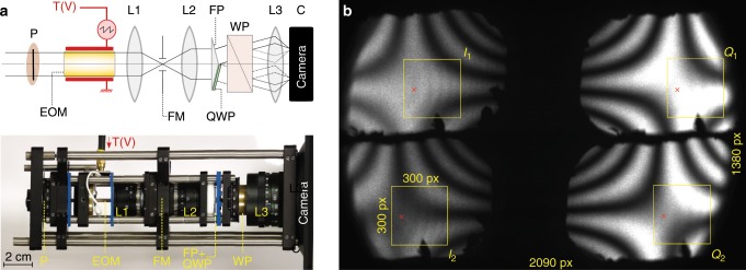
Fig. 5. Presentation of FAST-QUAD prototype.
a Schematic and photograph of the FAST-QUAD prototype. Due to the dimensions of the EO crystal employed ( mm), it was optimal to have it positioned after the input polarizer . This was followed by a focusing lens , a field mask (FM) at the intermediate image (that restricts the image spatial extent to prevent superimposition of the 4 sub-images on the camera), and thereafter a lens that recollimates the beam. A Fresnel biprism (FP) splits the beam into two, one part of which passes through a quarter-wave plate (QWP). Further propagation through a Wollaston prism results in 4 beams that are imaged onto the camera by means of lens , providing the four quadrature images. b Example of raw image acquisition when the FAST-QUAD prototype is illuminated with homogeneous light field. The four pixels quadrature sub-images , , and are delineated with yellow frames. The red cross indicates the position of the reference pixel used in Supplementary Note 2 to illustrate the quadrature mismatch correction algorithm implemented.

