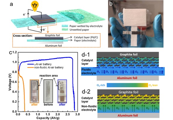
Figure 12.

(a) Scheme of a paper‐based μAl‐air battery. (b) A paper‐based μAl‐air pouch battery from top view. (c) Discharge curves of fluidic and non‐fluidic Al‐air battery. The insets in (c) are the optical images of the anode aluminum foils before and after discharge. (d) Schematic illustrations of cross‐sectional O2‐rich/lean electrolyte distribution in (d‐1) fluidic and (d‐2) non‐fluidic Al‐air battery. Reprinted with permission.58 Creative Commons license 3.0 (CC BY‐NC 3.0).
