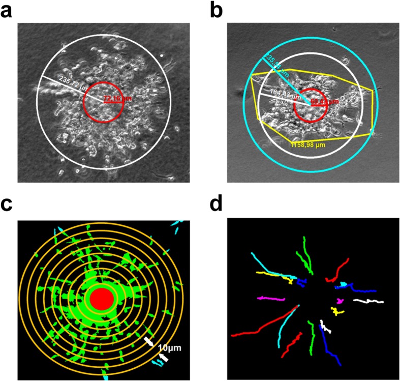
Fig. 7.

Quantification of migratory parameters. a Maximum migrating distance measured when cells evenly distributed in all directions. White circle, cell migration front. Red circle, size of bead. b Average of maximum migrating distance applied when cells showed uneven distribution in a shape of a polygon rather than a sphere. Yellow curve, cell migration front. White circle, calculated average of maximum distance. Light blue circle, maximum of cell migration front. Red circle, size of bead. c Schematic diagram to show the principle of computing migration area on the basis of the distance to the core. Cells are selected and filled with green. Light blue represents cells out of range. Red core is where the bead resides. Yellow concentric circles with radius difference of 10 μm are drawn to measure the migration area of increasing distance to beads. In this schematic the yellow circles do not have a radius difference of exact 10 μm but were only drawn to illustrate this quantification method. d Cell trajectories in collagen I between 55 to 70 h, tracked manually. Panels a-b show representative images of M14 cells, and panels c-d show examples of quantification on LLC cell images
