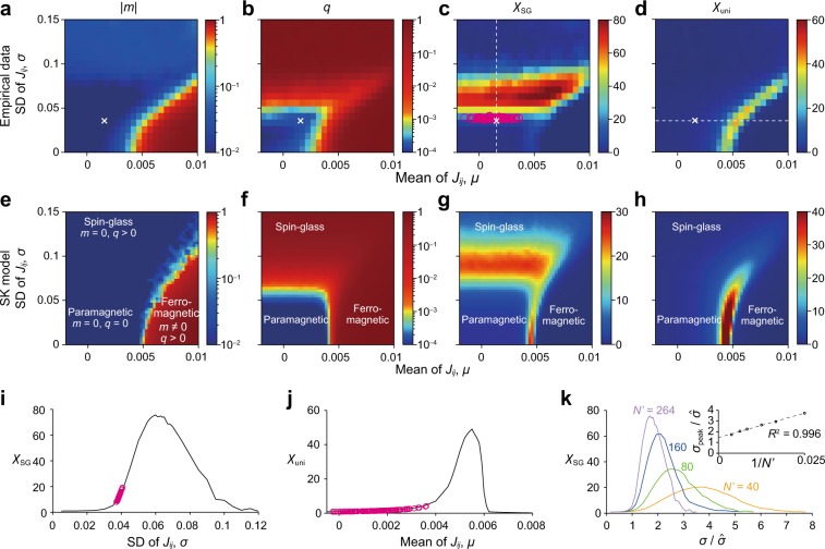
Fig. 1.
a–d Phase diagrams for the empirical data. e–h Phase diagrams for the SK model. a, e: ∣m∣. b, f: q. c, g: χSG. d, h: χuni. In a, d the crosses represent the mean and standard deviation of the Jij estimated for the entire population of the participants, i.e., (, ). In c a circle represents a participant. In a and e we plot ∣m∣ instead of m. This is because averaging over simulations and over realizations of J would lead to m ≈ 0 due to symmetry breaking, even if m ≠ 0 in theory such as in the ferromagnetic phase. i χSG as a function of σ, with being fixed. j χuni as a function of μ, with being fixed. In i and j, the curves are the cross-sectional view of c and d, respectively, along the dashed line in c or d. The circles in i and j represent the individual participants and are the projection of the circles in c and d onto the dashed line. k Scaling behavior of χSG when the system size is varied. The value of σ = σpeak that maximizes χSG is plotted against in the inset. The dashed line is the linear regression based on the six data points, , and 264. The coefficient of determination is denoted by R2.

