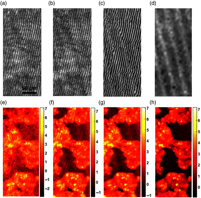
Fig. 2.
Demonstration of the -SMIM working principle: (a) left hologram, (b) right hologram, (c) -hologram, (d) its background term. (e)–(h) Phase maps calculated using single hologram, -hologram, filtered -hologram, and phase-shifting sequence, respectively. Scale bars in (e)–(h) represent optical phase shift values in radians.

