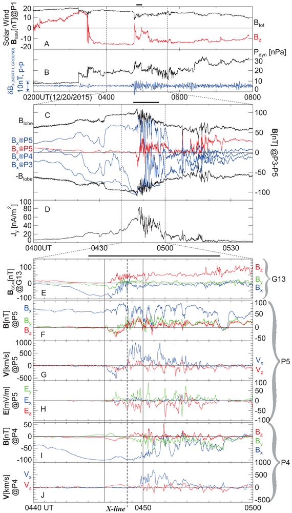
Figure 2 ∣. Overview of storm-time reconnection region encounter.
(A) Solar wind total (Btot) and GSM-northward (Bz) component magnetic field at ARTEMIS P1 (M1), located at (X,Y,Z)GSM= (−21, 54, −4)RE. In this and all subsequent panels showing vector quantities, black, blue, green and red traces correspond to the vector magnitude, and its X, Y, and Z components, respectively. (B) Solar wind dynamic pressure, Pdyn (black) at ARTEMIS P1, and X (northward) component ground magnetometer magnetic pulsations (variations) at Bay Mills (bmls), band-pass filtered with a 10s-120s window (δBX,(NORTH,GROUND)). (C) Magnetic field Bx at P3, P4 and P5; Bz at P5 only; and +/− Blobe (total field in the lobe) inferred from total plasma pressure at P5 assumed to be in pressure balance with the lobe (magnetic) pressure, overplotted for comparison with Bx. Note that when not explicitly defined, X,Y, Z components refer to the GSM coordinate system rotated about the ZGSM axis by ~10° to account for the approximate rotation of the field-line planes on THEMIS at that time (M2). (D) Cross-tail current density (Jy) between THEMIS satellites (M6). (E) G13 magnetic field, BGSM, in the GSM-proper frame; (F) P5 magnetic field, B; (G) P5 ion velocity V components: Vx, which is in the approximate reconnection outflow direction (+X), and Vz, which is parallel to the approximate inflow direction (±Z); (H) P5 measured electric field, E; (I) P4 magnetic field, B; (J) P4 ion velocity X and Z components, as at P5, in (G), above.

