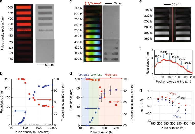
Fig. 3. Birefringence and transmission of laser written patterns with different parameters.
a and c Retardance (left) and transmission (right) images of birefringent structures written at different pulse densities and pulse durations, respectively. In c, the polarization was rotated during laser writing. b and d Plots of the retardance (blue circles) and transmittance (red squares) of the modified regions in a and c against the pulse density and pulse duration, respectively. In d, the ranges of the pulse duration for different modification types are indicated by different colours. e Retardance distribution in the area of birefringent structures written with different pulse durations. f Retardance plotted along the dashed line in e, where stress is formed between the laser written structures. g Refractive index change in the modified regions written with different pulse durations (Section 3 of Supplementary). The refractive index was measured using a phase imaging camera. Δnunpol, Δn0°,o and Δn90°,e are the refractive index changes measured with unpolarized light and with horizontally (0°) and vertically (90°) polarized light. The slow axis of birefringence in the modified region is horizontal (0°). The small difference of Δn0°,o > Δn90°,e at a shorter pulse duration is due to stress-induced birefringence

