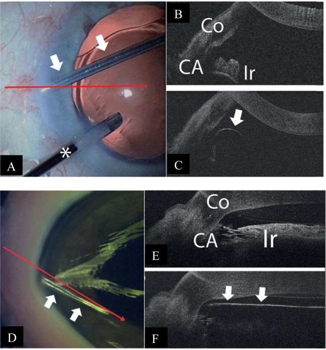
Fig. 4.
Intra-operative and iOCT images during trabecular aspiration Courtesy of Heindl et al. [18]. a The aspiration cannula (arrows) is placed within the iridocorneal angle. To maintain intraocular pressure, an irrigation cannula is additionally placed within the anterior chamber (asterisk). The horizontal line demonstrates iOCT scanning direction. b iOCT image of the iridocorneal angle before placement of aspiration cannula. Iris and trabecular meshwork are shadowed by scleral tissue (Co cornea, CA chamber angle, Ir iris). c iOCT image of the aspiration cannula (arrow) within the iridocorneal angle. With a non-parallel scanning direction, the tip of the instrument is difficult to visualise. d Aspiration cannula (white arrows) is placed within the iridocorneal angle of the porcine eye. The long arrow demonstrates the iOCT scanning direction. e iOCT image of the iridocorneal angle before placement of aspiration cannula in porcine eye (Co cornea, CA chamber angle, Ir iris). f iOCT image with placement of aspiration cannula (arrows) within the iridocorneal angle in porcine eye. The relation between the cannula tip to the trabecular meshwork and the iris is clearly visible. However, structures behind the cannula are shadowed by the cannula

