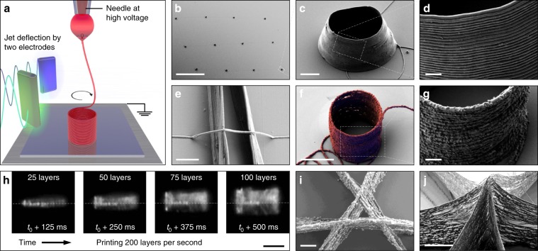
Fig. 5. Printing 3D structures.
a Schematic of the 3D printing of a cylinder. b–d SEM micrographs at different magnifications of PEO 3D cylindrical microstructures manufactured by EHD jet deflection printing. Scale bars (b–d): 200 µm, 5 µm and 1 µm. e SEM micrograph of a single suspended PEO fiber bridging a gap between 2 parallel nanowalls. Scale bar: 2 µm. f, g SEM micrographs of a PEO-Ag cylindrical structure printed using an ink containing 5 wt% 50 nm Ag nanoparticles. Scale bars: 5 µm and 1 µm. h High-speed video captures displaying the growth of a cylindrical structure at a frequency of 200 Hz. The jet of PEO ink had a diameter of ca. 200 nm and it is invisible on these captures (Supplementary Movie 2). Scale bar: 20 µm. i, j SEM micrographs of the crossing of three walls printed using an ink containing 50 nm Ag nanoparticles, where (i) is a top view of a crossing having a gap of 1 μm and (j) is a tilt view of the peak formed by walls crossing in one point. Scale bars (i, j): 1 µm and 5 µm. SEM micrographs (b–d, f, g, j) were taken with a 40 degree tilt, e with 30 degrees tilt, and (i) with no tilt. High-speed video captures (h) were taken at a shallow angle to the substrate. Image (f) was obtained by superimposing two images taken with secondary electrons and in-lens detectors, where printed fiber was false-colored in red and blue, respectively.

