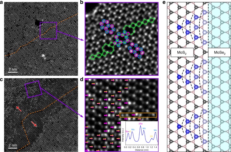
Fig. 6. Growth process of MoS2 channels.
a, b ADF-STEM images of intrinsic 60° GB (orange dashed line) within pristine monolayer MoSe2. Atomic arrangement of this GB (blue and purple circles: Mo and Se atoms; and green tetragons and octagons: 4 and 8 rings) resembles that in MoS2 nano-channels. c, d ADF-STEM images showing part of MoSe2–MoS2 hybrid winding channel. Some Se atoms has been replaced by S atoms, as indicated in d (purple arrows mark 2Se atoms and yellow–purple arrows mark S + Se atoms). Line intensity profile of 2Se, 2S, S + Se, and Mo atoms is provided in the insert of d. The red arrows in c represent the sulfidation direction. e A contour plot for the sequence (from blue to light gray) of substitution reaction along a zigzag MoSe2–MoS2 interface.

